It’s helpful to understand the big picture of an application before getting down into the details. The context diagram and the workflow diagram are two ways to show it. This big picture helps in creating acceptance tests for the system that have minimal redundancy and ease of maintenance. In order to demonstrate the two diagrams, I’ll use an example of an on-line ticket ordering system.
Context Diagram
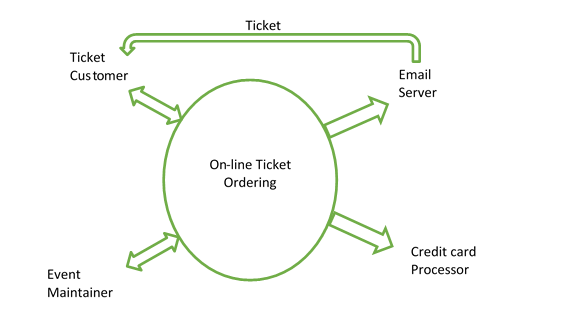
A context diagram shows the external entities with whom an application interacts. Those entities may be humans or they may be other systems. The circle represents the boundary between the application and the external entities.
In our example, a ticket customer places an order for a ticket for an event. The event has been set up by an event maintainer with the date, time, location, and seats. When the order is placed, a credit card charge is made to an external credit card processor. Then the ticket is the emailed to the customer.
More details of the data that is passed between the external entities and the application could be shown on the diagram. For example, the details of what information a ticket customer enters into the system could be included. 
The context diagram shows the external dependencies of an application. When automating tests for the system, these external dependencies should have test doubles (mocks) created for them. For this example, the two dependencies are the credit card processor and email server. If you don’t have a test double, you may max-out any credit card that was used for the testing.
Note, if you want to fully automate tests for the entire application, then you need test doubles for the ticket customer and the event maintainer.
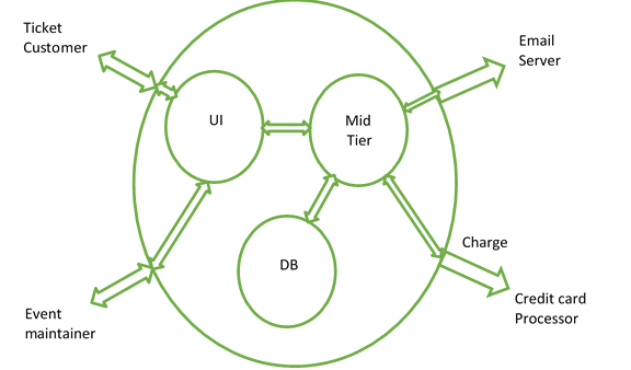
The previous diagram showed the external dependencies. An application usually has multiple components that interact with each other. We can show the context of those components by placing them within the application. In order to execute an external operation, the components communicate with each other via procedural calls, service calls, or some other mechanism.

Now the tests for external operations can be broken down into tests for each individual component. To test each component individually, the other components can have test doubles. In this example, to test the UI, there would be a test double for the mid-tier. To test the mid-tier, the same test doubles for the credit card processor and the email server would be used and an additional test double would be created for the database.
The tests for each component can then be broken down into tests for the modules (classes, methods, etc.) within that component.
Workflow Diagram
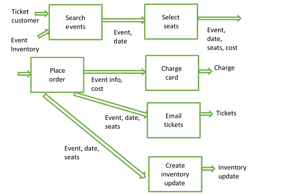
A workflow diagram shows the flow of a process, typically from the external view of the system. The diagram can detail the inputs and outputs to each step of a process. The flow may not necessarily be linear. There can be loopbacks in the flow. (This flow is often represented by a story map – see Jeff Patton’s Story Mapping).
For the example, the flow might look like the following diagram. The first step in the workflow requires an event inventory to be created. That’s part of the event maintenance workflow, which is shown later. This flow shows the “happy path” – seats are available, credit card has sufficient money available, etc. Exceptions could be represented in the same workflow, or different workflows, depending on the amount of detail to be shown.

The event inventory is created in a different work flow, such as:

Now each step in the work flow usually has a test created for it. Tests are often represented as Given/When/Then. In this form, it goes:
Given: Some initial state
When: An event or action occurs
Then: An output occurs or the state changes or both
The Given part of the test for a step usually comes from the Then part of another step. For example, for the charge card step, the given part comes from the place order step.
Given: Event information and a cost
When: Card is charged
Then: Charge is sent to credit card processor
Benefits of using the diagrams
The context diagram gives an idea of what external entities need to have test doubles. Those same test doubles can be used for component tests that communicate with those entities. Using the same test doubles minimizes redundancy and therefore increases maintainability.
The workflow diagram shows the connection between steps in a workflow. Tests for these steps should be placed in closely related files (or the same file) so that a the effect of a change in the output of one step can be easily traced to the input change necessary for the next step in the flow.